Aperture-to-wavelength ratio
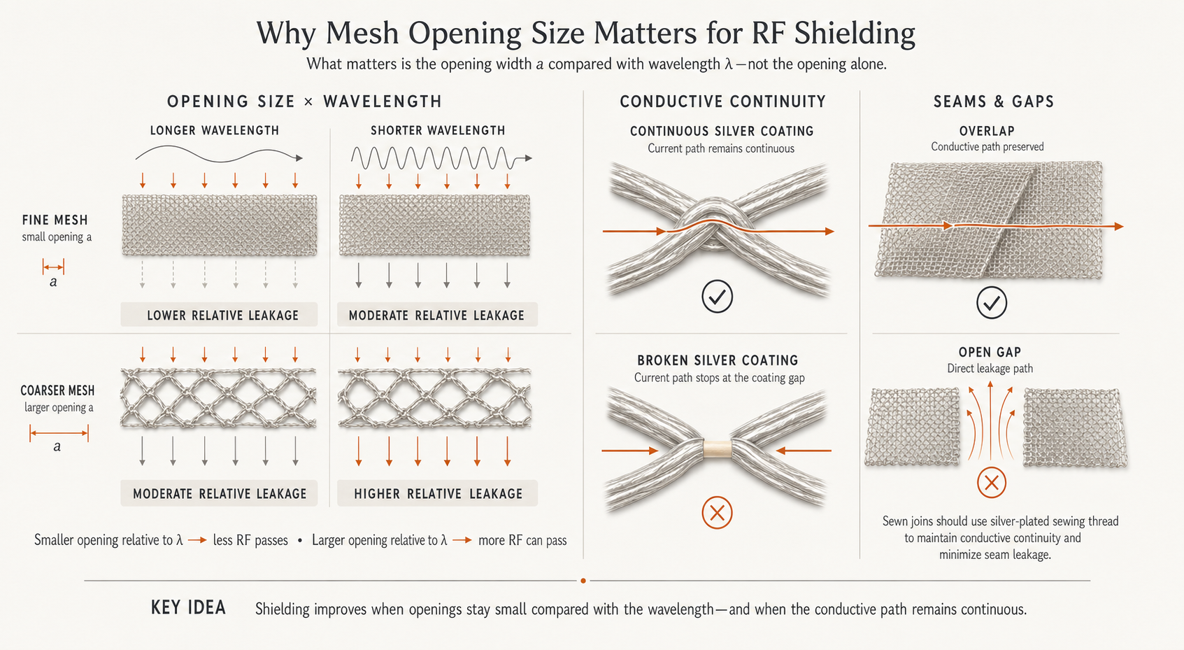
Compare the largest opening with the wavelength at the target frequency. Higher frequencies have shorter wavelengths, so the same opening can become more significant.
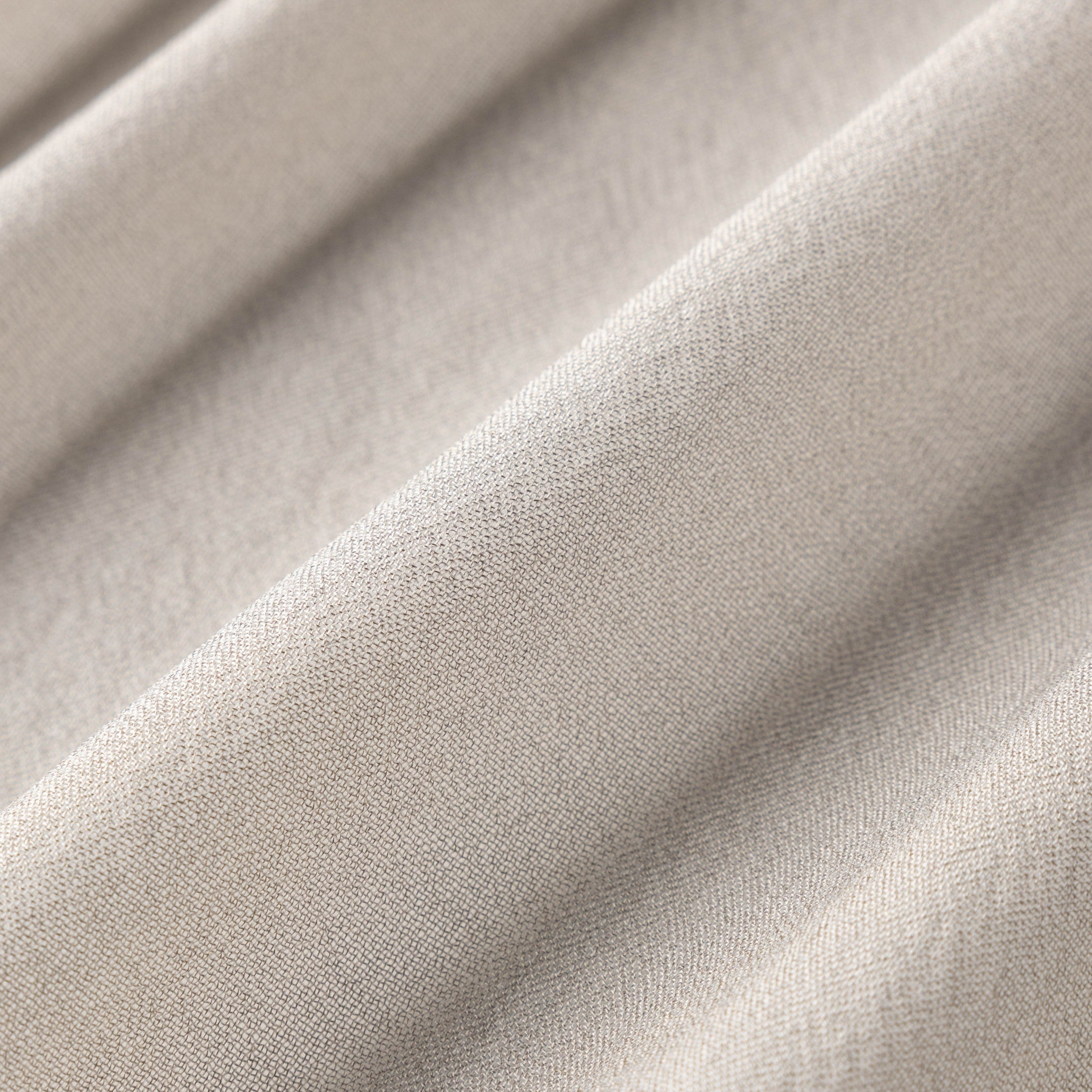
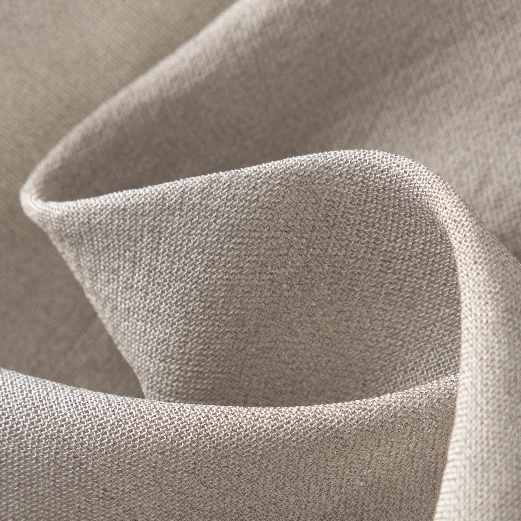
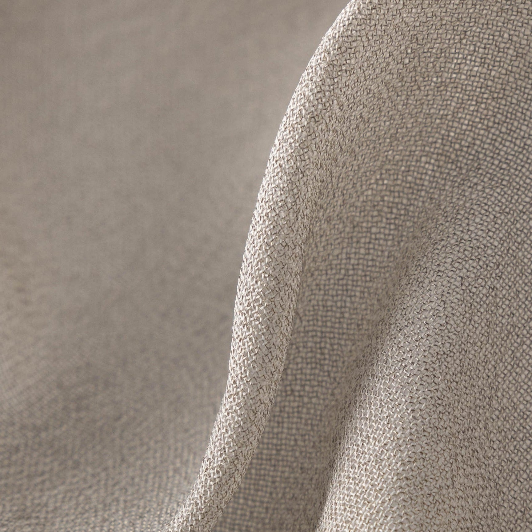
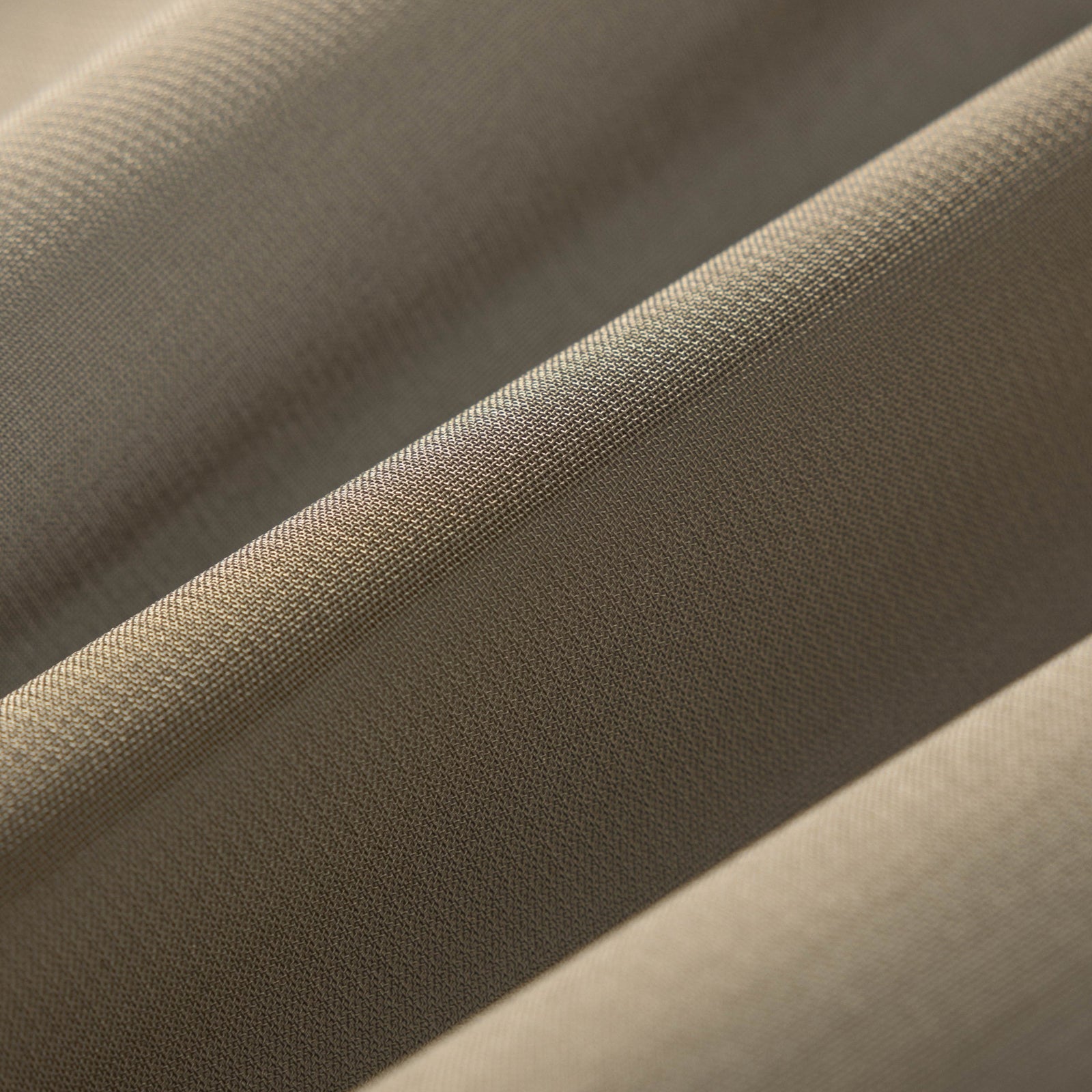
Durable Silver Nylon Fabric designed specifically for the construction of high-performance EMF tents, Faraday cages, and portable shielding enclosures. This dense material provides exceptional isolation.
Do not wash frequently. Wipe with a dry cloth. Avoid folding on the same lines to preserve silver coating.
APERTURE AND WAVELENGTH
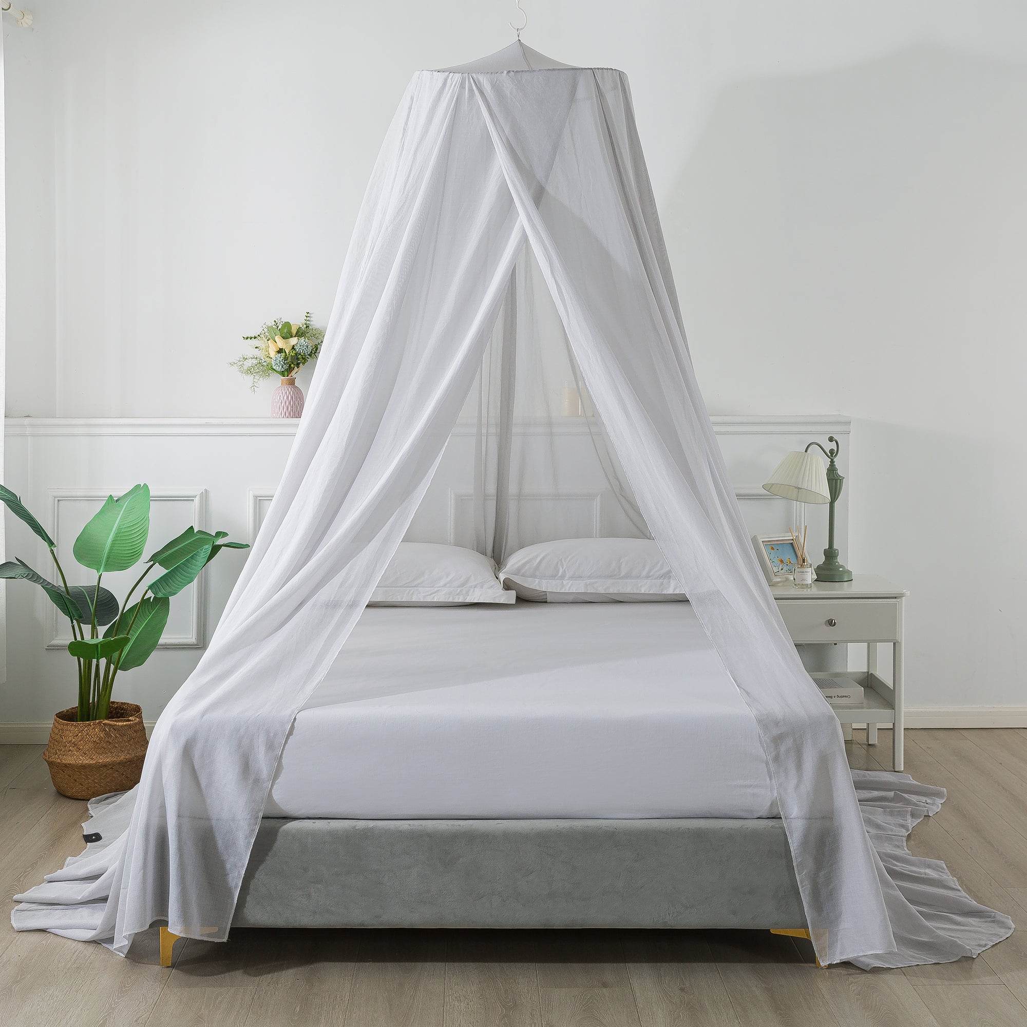
An opening is not automatically an unrestricted signal path. A conductive mesh acts as a repeated network of apertures: performance depends on the largest opening relative to the wavelength of the target signal and on whether conductive paths remain continuous.
When openings are sufficiently small relative to wavelength, the mesh can attenuate the field while remaining visibly open. As frequency rises, wavelength shortens and the same opening can become more significant. Actual results must be evaluated at the required frequencies and test conditions.
Compare the largest opening with the wavelength at the target frequency. Higher frequencies have shorter wavelengths, so the same opening can become more significant.
Surface resistance, coating continuity and yarn intersections affect the current paths that support attenuation.
Gaps, overlaps, closures and perimeter contact can change the behavior of a finished enclosure.
Frequency, incidence, polarization, sample fixture and test method all influence the reported result.
DESIGN TRADE-OFFS
These properties are related but not interchangeable. Photos cannot establish optical transmission, and visible pores alone cannot establish air permeability. Open-area ratio, aperture geometry, thickness, yarn density, finishes and assembly all matter.
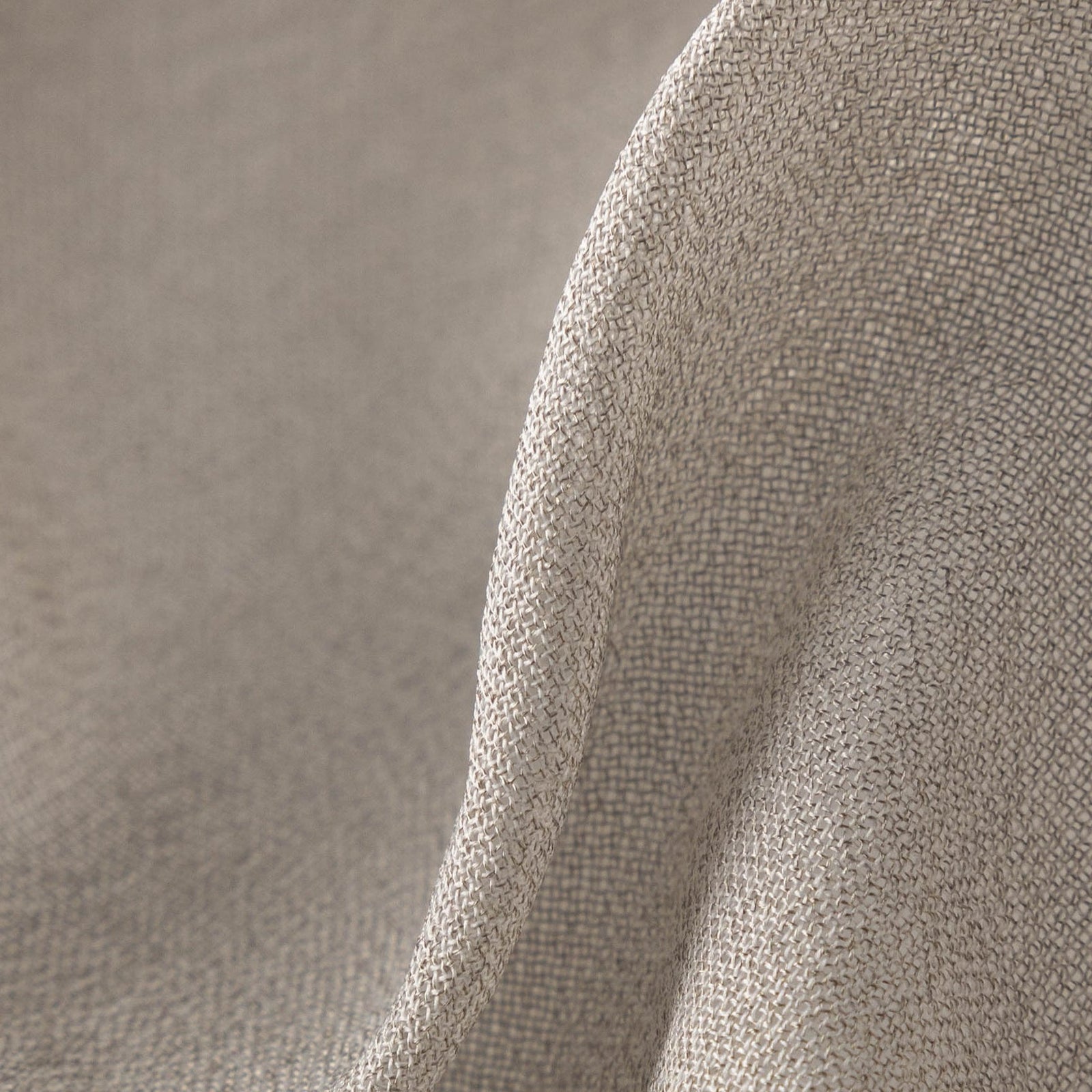
Smaller, denser openings often support greater attenuation for a given conductive system, but final results still depend on conductivity, frequency, continuity and setup.
Air movement depends on open area, pore geometry, thickness, yarn shape and finishing—not only whether holes are visible.
Backlighting and photography can make the same mesh appear more or less transparent. Use measured optical data when it matters.
CONSTRUCTION ROUTES
Mesh describes an open textile geometry, not one manufacturing method. The conductive path may be formed after the textile is made or built into the yarns used to make it.
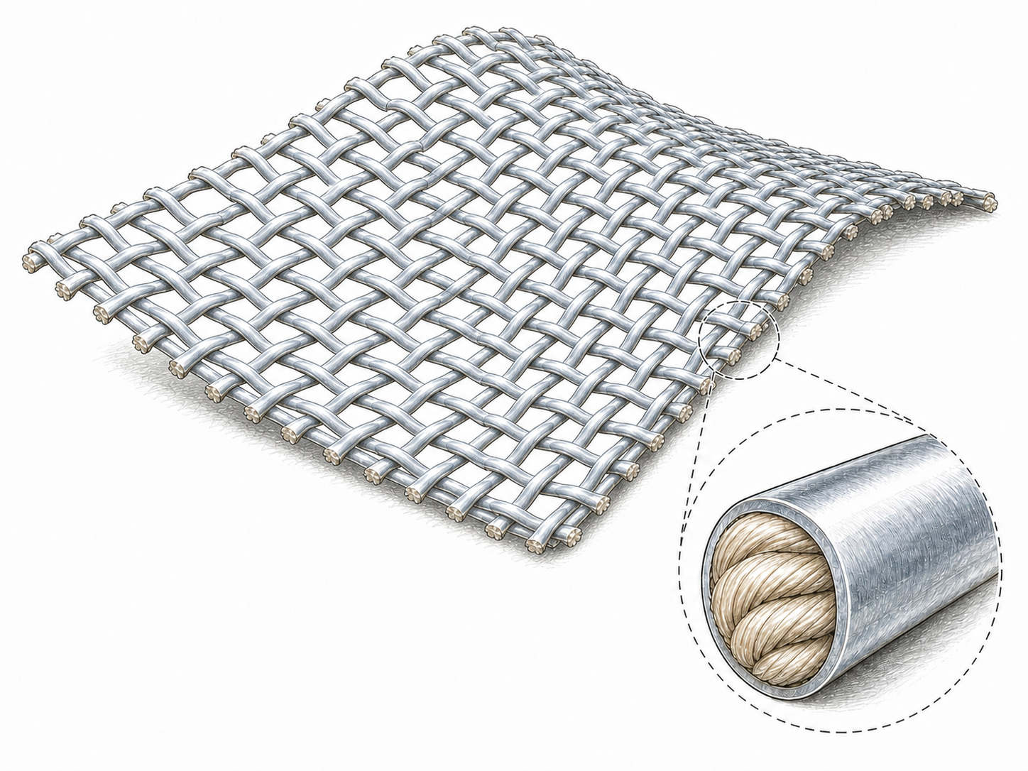
An open knitted, warp-knitted or woven substrate is formed first, then a silver or other metal conductive layer is created on the fiber surfaces.
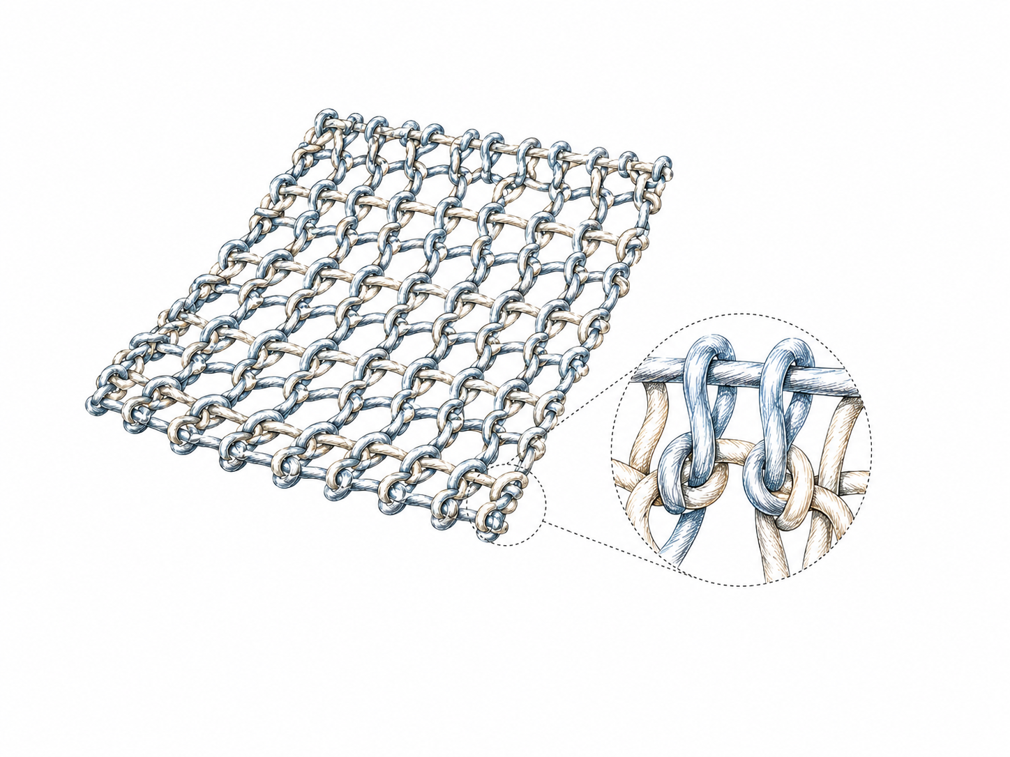
Yarns that are already conductive are knitted, warp-knitted or woven into an open structure.
MESH SELECTION
Metallic textile mesh is not a single construction. The substrate, conductive material and metallization level should be selected around the finished product—not only the target shielding value.
Our mesh products are conductive textiles, not rigid sheets of solid-metal wire mesh. A conventional metal screen can provide strong shielding at comparatively low material cost, but it is heavier, less flexible and unable to drape, fold or stretch like a textile.
Conductive textile mesh retains fabric-like handling, making it more practical for canopies, curtains, soft enclosures and other applications where flexibility, low weight or movement matters.
Silver, copper–nickel and other conductive systems can all be used to create shielding mesh, but they are not interchangeable.
Copper–nickel mesh can provide strong shielding performance and good cost efficiency. However, YUNJIA TEXTILE does not recommend it for bedding, apparel or other products intended for prolonged direct skin contact. For those applications, material selection should also consider skin contact, oxidation, hand feel and care requirements—not shielding performance alone.
Mesh can be developed from different textile substrates, opening sizes, widths and conductive treatments. The construction can be adjusted around the required flexibility, visibility, shielding level and project budget.
Even when a mesh is made entirely from silver-coated yarns, the amount of deposited silver can still be adjusted. A higher metallization level can reduce electrical resistance and may support higher shielding performance, while a lower loading can provide a more economical option for applications with moderate performance requirements. HC versions are developed for higher conductivity.
The final specification should be confirmed through resistance and shielding tests under defined conditions.